Making Cases for Smart Clothing Sensors With Vacuum Casting
Manufacturing Services: SLA 3D printing, CNC machining, vacuum casting, overmolding, painting, sanding and finishing
Materials:
Master Patterns – SOMOS 14120
Prototypes – UPX8400 Urethane, PX5210
Quantity: One master pattern (four pieces); 10 complete sets of cast copies
Lead Time: 11 days
The Customer
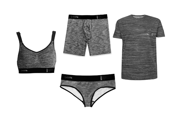
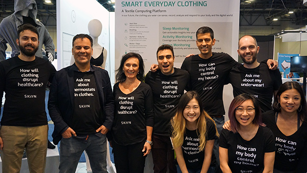
SKIIN was created by the team at Myant. They developed the product with the belief that smart textiles with embedded electronics are the gateway technology for enabling a smarter and better human being. They recently approached us for support to manufacture prototypes for them.
The Product
SKIIN is a line of everyday wearable clothes that contain a multi-function biosensor. This rechargeable multi-sensor connects to your smartphone where a proprietary app analyzes biometric data and provides actionable feedback to help users stay more calm, focused, healthy and productive. It can interact directly and automatically with other connected IoT devices for real-time lifestyle enhancement.

The Project
Myant approached us to help them develop a set of rapid prototypes for their major product introduction at CES 2018. These prototypes needed to be showroom quality, identical in fit and finish to eventual production versions.
Time was limited, so we advised using SLA 3D printing to make a set of master patterns, from which we could then make multiple copies using polyurethane vacuum casting. This method is one of the fastest and least expensive ways to make rapid prototype copies in plastic without making hard production tools.
Making The Master Patterns
Master patterns are the first step in the vacuum casting process. Masters can be made from any stable solid that is reasonably heat-resistant. We used SLA (stereolithography) 3D printing and SOMOS 14120, a photocuring resin with properties similar to ABS engineering plastic.
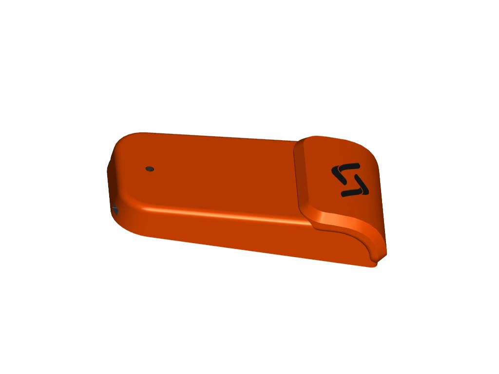
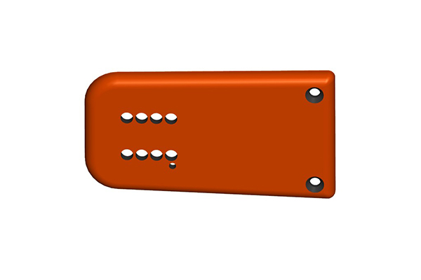
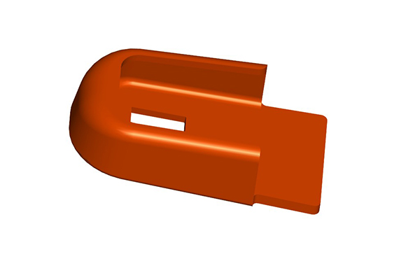
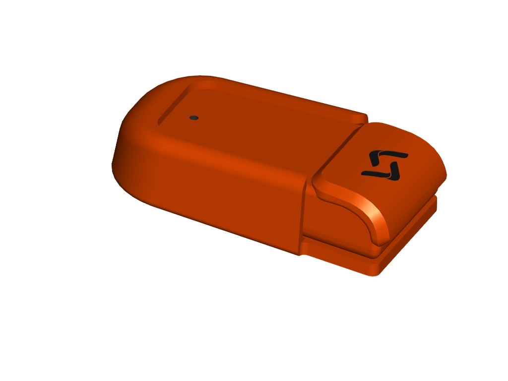
The prototype consisted of top and bottom cover plates, into which will go the electronics to be assembled later. The sensing unit will then fit into its companion dock.
With the client’s 3D CAD file in .stl format, we were easily able to prepare a program for our SLA printer.
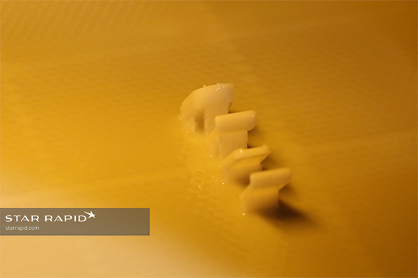
A UV light was used to cure layers, starting from the top and working down. For viewing purposes we used an orange light because it doesn’t photoreact with the polycarbonate resin.
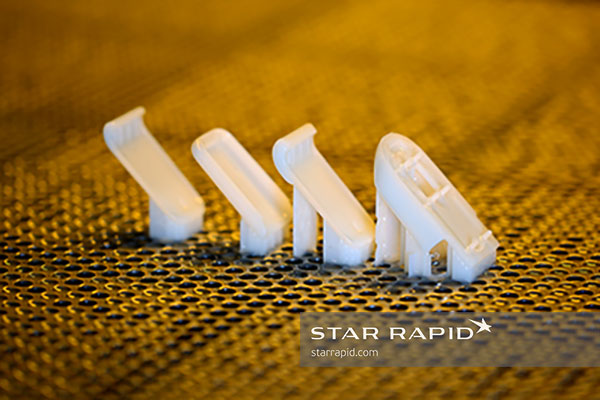
Parts were angled at approximately 45° for better print resolution. Supports were also a necessary part of the build design. Later we trimmed these off and sanded the remaining surfaces smooth.
We printed four separate pieces for the patterns, although only three go together to make a complete set. The fourth piece was used to form the overmold, which we’ll discuss later in the study.
Finishing the Masters
SLA printed parts tend to have a rough, unfinished look so we sent the patterns to our model shop for wet sanding.
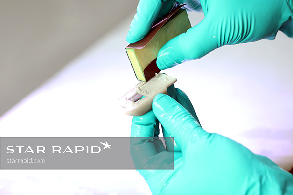
We actually want to have a textured pattern on these prototypes, but only a very specific texture in certain areas and not others. Therefore it’s best to sand down to the common base and then build it back up later.
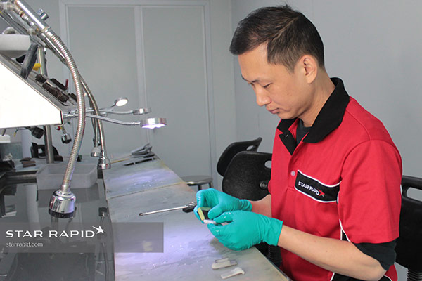
After wet sanding in progressively finer grits, we moved the parts to the painting department for the next step.
Painting
In this case we weren’t interested in painting for cosmetic reasons, since the master pattern will only be used to make copies of itself. However, painting can be used to accomplish two other important goals. First, it sealed micropores in the surface and therefore created more uniform copies. And we used a special painting technique to apply textures.
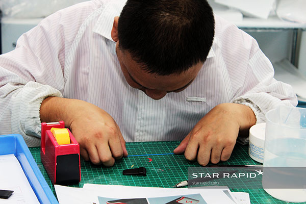
First the entire piece was sealed with one uniform coat. The overmolded rubber edge around the raised cover was to be left smooth so this area was carefully masked off. After all, one of the secrets to getting great painting results is knowing what not to paint.
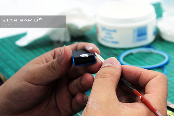
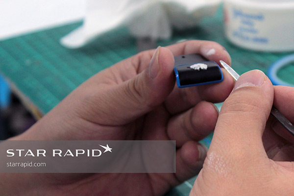
These parts have a recessed design in the top cover. The customer needed this area to also remain untextured but it’s a hard place to mask. What to do? We used talcum powder and a little water to make a soft paste. This filled the recess and was easy to remove later. And it looked kind of cool too.
Getting the right texture required fine control of spray volume, gun pressure, coating thickness and distance from the workpiece.
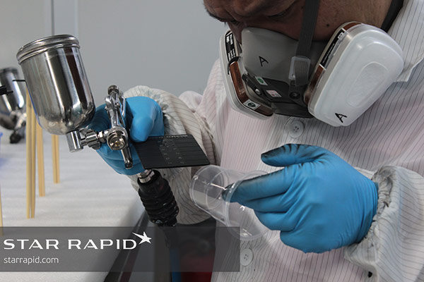
Our technician experimented on test pieces that had the same initial surface finish. This helped him to calibrate his equipment and technique. He then compared these results to a standard surface texture gauge.
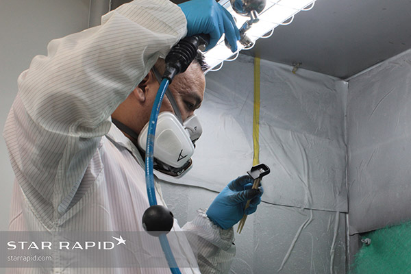
Our technician slowly misted over the surface in several light passes, building up a thicker coat composed of fine paint droplets that partially dried in the air before they settled on the part. This is the secret of a painted texture, and it’s not easy to do right.
Vacuum Casting Molds
After the masters were finished, we moved them to our vacuum casting department to prepare the silicone molds.
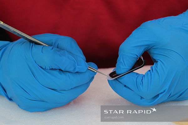
Before we could put the masters into the casting box, we placed a thin skirt of scotch tape around the edge. This forms the parting line, making it easier to open the mold later.
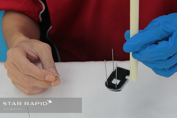
Casting boxes don’t need to be anything fancier than simple aluminum plates hot-glued together to form a seal. They can be reused on other jobs multiple times.
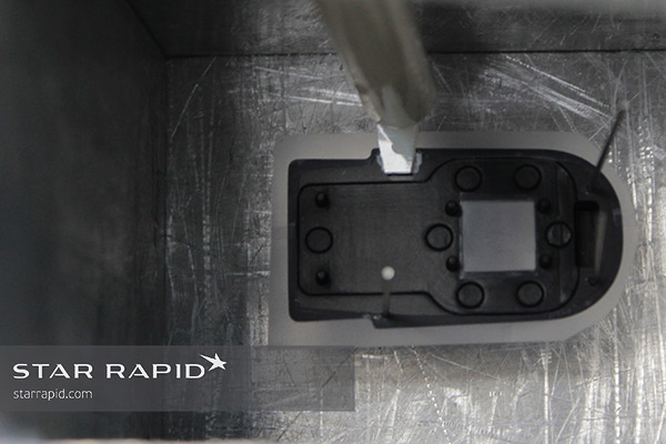
The purpose of the dowel rod is to hold the part suspended a few inches above the bottom of the vacuum casting box. This allows it to be surrounded on all sides by liquid silicone.
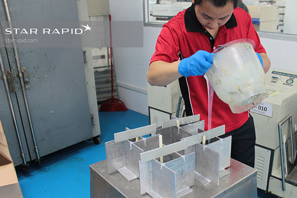
Silicone was heated and stirred well in advance to remove air bubbles while helping it to flow easily. These casting boxes were then placed into an oven and the molds were cured for at least sixteen hours.
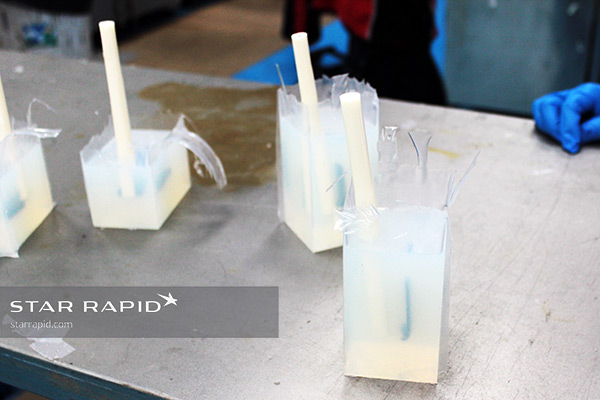
After curing, we broke open the casting boxes to reveal the molds inside. Now it was time to remove the master patterns from the molds.
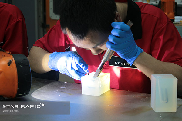
After removing the dowel rod, we used a strong light source to clearly illuminate the outline of the part. Our technician needed to cut carefully into the mold but not damage the part itself, a kind of surgery informed by long experience.
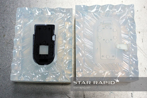
This cavity is now a high-fidelity negative image of the original part. Notice also the smooth perimeter around the part shape, caused by the skirt of scotch tape we used to form the parting line.
Vacuum Casting Copies
Now that we had accurate molds of our master patterns, we used those to produce a series of copies.
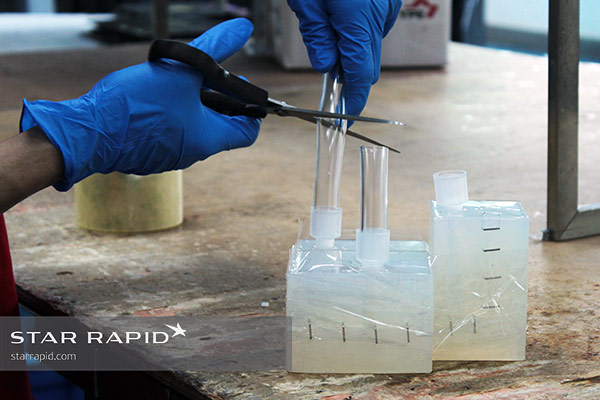
The now empty mold halves were put back together in the correct orientation, stapled and sealed shut. Spouts and filler tubes were used to feed resin into the cavities.
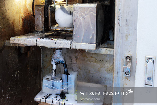
Black PX5210 resin was mixed and heated for ten minutes in the vacuum chamber. The mold itself was preheated for more than three hours to achieve equilibrium temperature with the casting resin. When ready, this resin was poured into the feed tubes, the cavities filled and the door of the vacuum chamber sealed shut.
Vacuum is used to force material out of the vent holes, ensuring that all internal cavities of the part’s shape are fully filled with resin.

After curing for at least 3 hours, we removed the staples and opened the casting mold. This yielded a nearly perfect copy of the master pattern, including the fine grain of the surface texture. Dimensional accuracy was also more than acceptable for prototyping purposes.
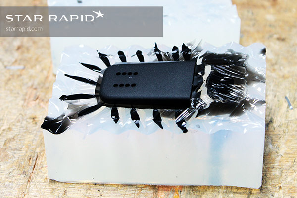
Minor flash around the edge of the part was created by resin being pulled through the vacuum vent holes. This was easily trimmed off in our model shop.
We were not quite finished, since the top cover also has an overmold. This is how that process works.
Overmolding
One of the advantages of vacuum casting is that it makes possible the use of overmolding, which is the combination of two or more different casting materials, with different properties, into a single finished piece.
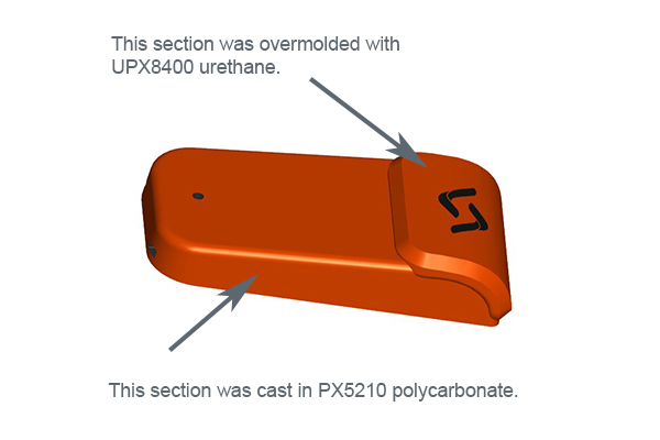
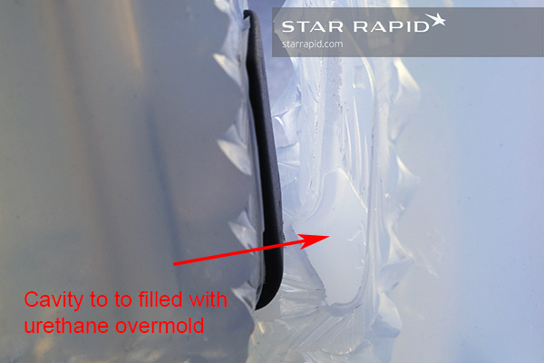
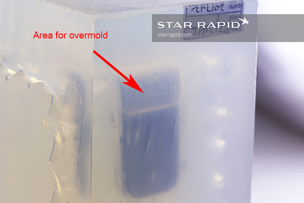
We printed a master pattern in the shape of the completed top cover. This pattern was used to form a silicone mold, and that mold in turn produced a hollow cavity.
Then, a different pattern of the top cover, similar in shape to the full size one but lacking the raised section, was placed back into that cavity, leaving an unfilled gap. In a second casting step, we poured urethane resin back into the mold which filled this cavity, creating the finished overmold.
This overmold provided a soft rubber grip, convenient for when users grab the unit to slide it into or out of the dock.
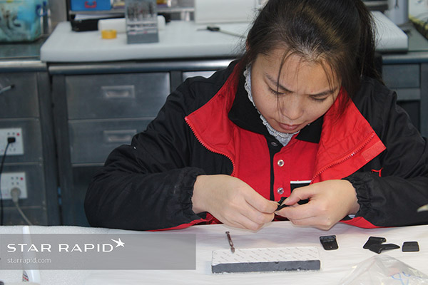
In addition to cleaning off any leftover flash, we had one more assembly job to perform before we sent the prototypes to quality control for measurement. We glued a small, clear acrylic lens onto the front cover. This will be a window for an LED indicator light to be installed later.
Inspection and Measurement
Although these are not full production-ready parts, they needed to meet all of the same cosmetic and performance citeria.
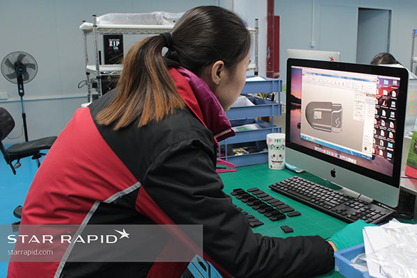
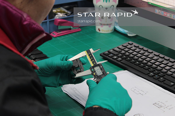
We checked all of the major dimensions of each part and compared them to the specifications from the customer’s original drawings.
Parts were approved, packaged and shipped, well in time for the customer to prepare them for CES 2018.
